Table of Contents
- 1. Introduction
- 2. System Overview
- 3. Quality Concept
- 4. Architectural Concept
- 5. System Design
- 6. Subsystem specification
- 7. Technical Concepts
- 8. References
Changelog
| Version | Date | Author | Comment |
|---|---|---|---|
| V0.1 | 04.11.2021 | Lukas Ernst / Florian Kellermann | created |
| V0.2 | 05.11.2021 | Lukas Ernst | Add introduction and glossary details |
| V0.4 | 07.11.2021 | Lukas Ernst | Add runtime and non-runtime quality goals |
| V0.5 | 10.11.2021 | Lukas Ernst | Update quality concept and technical concept |
| V0.6 | 12.11.2021 | Lukas Ernst | Update usability concept |
| V0.7 | 16.11.2021 | Lukas Ernst | Add architectural concept |
| V0.8 | 26.03.2022 | Lukas Ernst | spicify architectural concept |
| V0.9 | 10.04.2022 | Lukas Ernst | Add system design |
| V1.0 | 13.04.2022 | Lukas Ernst | Update system design |
| V1.1 | 14.04.2022 | Lukas Ernst | Update subsystem specification |
| V1.2 | 20.04.2022 | Lukas Ernst | Correct descriptions and add links |
| V1.3 | 24.04.2022 | Lukas Ernst | Latest changes |
| V1.4 | 06.05.2022 | Linus Eickhoff | Checked for correctness |
1. Introduction
The aim of this project is to program a standalone application for Windows based on a plugin for the AutomationML editor. The graphical user interface should be improved and support the modelling of sensors according to IEC 60947-5 should be offered. Furthermore, it should be possible to create devices, add device interfaces and file attachments. It should also be feasible to create a device manually, but also by reading in existing device description files with the aid of the DD2AML converter. The output should be an AutomationML package that complies with the rules for AML component models (AML-DDs). The programme is aimed at an industrial user group, as it is suitable for creating models, which should help in the design of systems.
1.1 Glossary
AML Automation mark-up language is an open standard data format for storing and exchanging plant planning data
AMLX AML Package to store also not AML files in one package
CAX File format of AML Device files
C# High level language often used for programming
GUI Graphical User Interface
.NET The .NET Framework is a software development and runtime environment developed by Microsoft for Microsoft Windows
IODD Means IO Device Description and describes sensors and actuators
GSD General Station Description, data format for Profibus and Profinet devices
2. System Overview
2.1 System Environment
The standalone application can only be accessed via Windows, as this operating system is used as the platform. The application can be installed and the graphical user interface can be used via this platform. In contrast to old programme or the plug-in, the editor and the "IODD" and the "GSD" converter no longer needs to be used.
2.2 Software Environment
For the standalone application to work, you need at least version 4.5 of the .Net framework, as C# was used developing it. This version of the framework is available from the "Windows Vista" operating system variant onwards. You do not need any further software, as this is a standalone application.
2.3 Quality Goals
In order to achieve the quality goals, different criteria are considered.
2.3.1 Runtime quality attributes
These can be observed at execution time of the system.
2.3.1.1 Usability
Usability is the most important aspect of the project besides the standalone application. To this end, a graphical user interface was created that allows the user to use it as easily as possible. Intuitive operation is very important, but an appealing design is also necessary to create the best possible user experience. This is the only way the application can successfully simplify work processes (More information in the Usability Concept).
2.3.1.2 Functionality
As the targets have been set relatively precisely, attention should be paid to their compliance and fulfilment. Furthermore, care should be taken to process the functions according to their importance, which means ensuring the standalone property first, then the usability and then the remaining functions.
2.3.1.3 Performance
The problem with programmes that have been developed many times and then by different teams is that they often have poor code quality and therefore a high RAM and memory load. On technically older systems, this can lead to problems such as crashes or slow feedback. This is also a problem of the plugin, there are single files with several thousand lines of code. So we should at least try not to make this worse. If we have enough time, we should adapt the code in general. You can find more information about this in the section Code Quality.
2.3.1.4 Security
It must be ensured that it is recognisable where and from whom the programme originated. It will not be possible to access the Internet with the programme, so confidentiality is automatic. But it should be downloaded from an official source, the releases can be found here.
2.3.1.5 Availability
The programme and its code will be available on GitHub on a public repository. This means that anyone can access the programme at any time.
2.3.1.6 Interoperability
This is important because it must be ensured that users are not firmly bound to this standard or programme. After all, the main users will come from the industry and therefore place a lot of value on a uniform standard. More information can be found in the Technical Concept.
2.3.2 Non-Runtime quality attributes
These cannnot be observed at execution time of the system.
2.3.1.1 Modifiability
Since the programme is open source and publicly viewable, it can be extended by anyone. This is important if any use cases arise in the future.
2.3.1.2 Portability and reusability
Attention is paid to transferability to later projects, through the involvement and formation of libraries and the like, but the application case is very specific and difficult to transfer to other or new projects. Therefore not so important.
2.3.1.3 Testability
This is probably the second most important point after usability, care must be taken to ensure that the code is testable. On the one hand directly in the code, but also testing the binary is important. For this purpose, various test cases are described and worked through on the Systemtestplan page. Also check the Systemtestreport to learn more about the test results. The AML Component Checker should be validating all created AML files. Thereby, to keep quality high, errors that cause undesirable behavior or even fatal errors must be eliminated.
3. Quality Concept
This part of the software architecture specification explains and breaks down the problems that usually arise during the further development of software. This includes concepts for dealing with these problems and thus improving the quality of the final product.
3.1 Usability Concept
The criteria for good usability are:
Intuitiveness : Intuitiveness is a key component of good usability which means that the user understands the application without a long training period. This point is also interesting for companies, as they then do not have to train their employees for so long. This is to be achieved by having important things at the top and not hidden in a drop-down selection. Furthermore, the design must be adopted from other well-known programmes.
Design : When designing the application, an appealing layout is important. It should be clearly recognisable which function is hidden behind which visual elements and how the user can navigate through the app. It probably makes sense to be inspired by the design of the AutomationML editor, because then the switch to this programme would not be so difficult.
Recognition value : This means that similar functions should be realized with the same sequences. This makes it easier for the user to find his way around the functions and increases user friendliness. For example, when creating models or a wizard that guides you through the creation.
Colour scheme : A good colouration can be created by an attractive choice of colours and their coordinated contrasts. At the moment, matte colours are more in vogue and are preferred for designs. Many people find these more pleasant.
Implementation guideline:
After conducting the usability test, guidelines were developed on the basis of which the GUI improvements will be made. Therefore, the GUI must meet the following guidelines:
- A consistent colour palette should be used, where elements with the same events have the same colours for recognition. Matte and colour-coordinated palettes should be used here.
- Contrasts, borders as well as roundings should be used to emphasise inputs or interaction fields. Blank areas should be created to give an attractive and uncluttered design. Another advantage is that the user will then find his way around more easily. The layout of the GUI should be independent from the style of the AML editor, as this is no longer up to date.
- The design and layout should be self-explanatory and reinforce the previous point to allow intuitive use.
Based on the criteria just defined and the guidelines developed, the graphic interface is adapted and optimised. Functionality is very important but should not negatively affect usability. Nevertheless, compromises have to be made in terms of feasibility, as the basic concept of AutomationML should be presupposed.
3.2 Code Quality
Code quality is one of the most important aspects when it comes to software that is being developed further and may come from different developers. For this reason, we have made it our mission to address and improve the problem of code quality. To maintain a certain standard, we have agreed on certain conventions:
- Commenting on sections of code that are not clearly understandable in order to explain the implemented idea to others
- Programming paradigms and programming principles that make the code easy to understand, such as one main function per file and a sensible folder structure.
This means that the code is indented uniformly to improve readability and comprehension. Furthermore, the program is divided into modules that can then be imported and used. Otherwise, you run the risk of having to write duplicate code. In addition, it is our responsibility to write documentation that records which ideas have been implemented and how, so that the existing functions are easier to understand for future developments and can be built upon.
4. Architectural Concept
4.1 Architectural Model
The application was designed and developed according to a Model-View-Control (MVC) architecture pattern that resembles a cycle. The user can use the application by accessing the GUI. However, the actions he performs in the GUI are not processed in the GUI but in the controller and its subclasses. The controller executes the changes in the background, these are also called manipulations. Afterwards, the changes are updated on the user interface so that the user thinks that the changes were made directly in the GUI (cf. Figure 1).
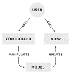
Figure 1 - MVC Architecture
Almost all the logic is contained in the controller, which thus forms the centre of the entire system architecture and contains the functionalities. There is basically only one layer that is accessible to the user, the GUI.
The controller is the main control unit from the plug-in. It is responsible for communicating with the user interface and the external systems that are added for conversions. This interface is the heart of the entire application and is responsible for the functionalities, but also for the integration of additional functions such as saving or loading AMLX packages from the AutomationML Engine. Thus, the concept builds on that of the plug-in, making it easier to adapt functions and ideas. The change is that it will be a standalone application. This is ensured by integrating the AutomationML engine and the plug-in into a new programme via an import. The plugin is then started in its own view, so that the old code of the plugin is retained.

Figure 2 - Logic of the plugin
In the figure above, you can see the new architecture design that depicts the structure of the standalone application (cf. Figure 2). As you can see in the illustration, the user only interacts with the graphical user interface. This then passes the input from the user to the controller and the controller displays the information in the GUI. The controller processes the requests with the help of the AutomationML engine, but not all functions were mapped for this because there would be too many. For example, it can be used to save and load models in AML format. To be able to process IODD and GSD model formats, the programme needs converters. These work with two interfaces and return an AutomationML file. However, due to the further development based on the project, the architecture became more and more unstructured and complex. As a result, MVC is no longer used as intended. This was further complicated by the use of a Microsoft Forms application. Ultimately, as can be seen in Figure 4 and 5, the architecture became increasingly unstructured and complex.
5. System Design
The idea of making the plugin a standalone application is to run the plugin on another programme that provides the appropriate dependencies. This gives the impression of running the plugin directly (cf. Figure 3).

Figure 3 - Programme Concept
The advantage of this solution is that the code of the plug-in remains largely intact. This makes it easier to adopt the ideas and insights of the old team. The programme on which the plug-in runs is shown in figure 4.

Figure 4 - Class design from the main application
The "Program" field in the diagram is supposed to represent an executable file; if you click on it, "Form1" is called. This function then loads the "ModellingWizard", i.e. the plugin. This means that the GUI of the plugin is then displayed in "Form1".

Figure 5 - Class design from the ModellingWizard
The current design of the plugin has changed a little, but not much (cf. Figure 5). The concept of the plugin and most of the code was taken over from the old project.

Figure 6 - MVC pattern
Still the MVC pattern is a small part of the whole system design (cf. Figure 6). In this case the InputFromUser is obviously the user input. DeviceDesc (standing for Device Description), due to its two different C# program files, once maps the GUI and once the controller. DataMW is the class that takes care of the data management and creates an object of the type MWData, which can then export, store and process through the controller. The source code is located in the "main" branch under the "Source" folder. Click to open the Source folder.
| Classname | Storage location |
|---|---|
| About | SOURCE/Plugin/About.xaml.cs |
| AnimationClass | SOURCE/Plugin/Animationclass.cs |
| AutomationMLDataTables | SOURCE/Plugin/AutomationMLDataTables.cs |
| ClassOfListFromReferenceFile | SOURCE/Plugin/ClassOfListsFromReferencefile.cs |
| DeviceDescription | GUI: SOURCE/Plugin/DeviceDescription.Designer.cs Logic: SOURCE/Plugin/DeviceDescription.cs |
| ModellingWizard | SOURCE/Plugin/ModellingWizard.xaml.cs |
| MWController | SOURCE/Plugin/MWController.cs |
| MWData | SOURCE/Plugin/MWData.cs |
| MWDevice | SOURCE/Plugin/MWDevice.cs |
| Resources | SOURCE/Plugin/Resources/ |
| SearchAMLComponentFile | SOURCE/Plugin/SearchAMLComponentFile.cs |
| SearchAMLLibraryFile | SOURCE/Plugin/SearchAMLLibraryFile.cs |
6. Subsystem specification
6.1 MOD.001: Graphical User Interface (GUI)
| <MOD.001> | Graphical User Interface |
|---|---|
| System requirements covered: | /LF10/, /LF30/, /LF40/, /LF50/, /LF60/, /LF70/, /LF80/, /LD20/ |
| Services: | The graphical user interface is taking input from the user and sending it to the controller by calling event functions. |
| Interfaces: | --- |
| External Data: | --- |
| Storage Location: | SOURCE/Plugin/DeviceDescription.Designer.cs |
| Modul documentation: | MOD.001: Graphical User Interface (GUI) |
6.2 MOD.002 Controller
| <MOD.002> | Controller |
|---|---|
| System requirements covered: | /LF10/, /LF20/, /LF30/, /LF60/, /LF70/, /LF80/, /LD10/, /LD20/ |
| Services: | Logic distribution is handled by the controller. It is reacting to the events triggered by the GUI and takes care of creating the respective objects. Also the input and output functions are implemented in the controller. |
| Interfaces: | Interface of AMLX packages. For export/import of amlx files there is another class referenced: SOURCE/Plugin/MWData.cs |
| External Data: | --- |
| Storage location: | SOURCE/Plugin/DeviceDescription.cs |
| Modul documentation: | MOD.002: Controller |
6.3 MOD.003 Runtime
| <MOD.003> | Runtime |
|---|---|
| System requirements covered: | /LF40/ |
| Services: | This part of the programme turns the plug-in into a standalone application. The goal is that it has the same feature set as the AutomationML editor on which the plugin runs. |
| Interfaces: | --- |
| External Data: | --- |
| Storage location: | SOURCE/Application/Program.cs |
| Modul documentation: | MOD.003: Runtime |
7. Technical Concepts
7.1 Persistence
By using the publicly available "AMLX" package standard, the system becomes persistent. This means that created or edited models can be reopened and edited in the AutomationML Editor. This function is particularly important in an international and industrial environment. Therefore, "IODD" and "GSD" files can also be converted.
7.2 Communication with other IT-Systems
The plug-in already had the problem that it was dependent on external programmes. Thus, "IODD" and "GSD" programme types had to be converted in order to be able to use them. The goal will now be to implement these programmes or converters directly in the standalone application. The advantage of this is that the user does not have to install external dependencies that may also cause errors. This means that, in the best case, there would only be interaction with the file system. This model can also be seen in the Architectural Model.
7.3 Deployment
To make changes to the application, Visual Studio 2019 must first be installed. In "Visual Studio 2019", the file "Application.sln" from the "Application" folder must then be opened.
The application and the plug-in (ModellingWizard) are then visible in the Solution view.
In order to be able to compile the application, the "AML.Engine" package in version 1.5.8 may have to be installed via the "NuGet" package manager.
7.4 Data validation
All data checks are running in the background, invisible for the user. The controller is checking for missing information and incorrect entries, that must be specified as mandatory information.
7.5 Exception handling
Exception handling is necessary to prevent errors caused by the user while using the program. So called "try-catch" blocks are used to 'catch' these and prevent unwanted or incorrect behavior of the software. This way, the user is informed about what did not work and he/she may be able to fix the problem or at least report it to the developers.
7.6 Internationalization
The whole system layout can be used for international purposes since the user manual and over all GUI is written in English and English is defined to be the international traffic language. On the other hand, there is no way to change the language so English is a mandatory knowledge for using the program.
8. References
| Reference | Source |
|---|---|
| [1] | https://faq.arc42.org/questions/C-1-2/, 20.04.2022 |
| [2] | https://github.com/DekaAthlos/TINF19C-ModellingWizard/wiki/2.-Software-Architecture-Specification, 21.04.2022 |
| [3] | https://www.perforce.com/blog/alm/how-write-software-requirements-specification-srs-document, 21.04.2022 |
| [4] | https://books.google.de/books?id=7pVbAgAAQBAJ&lpg=PA1&ots=3l-6o0BDrw&dq=clean%20code%20robert%20martin&lr&hl=de&pg=PA1#v=onepage&q&f=false, 22.04.2022 |
| [5] | https://blog.iandavis.com/2008/12/what-are-the-benefits-of-mvc/, 22.04.2022 |
| [6] | https://www.youtube.com/watch?v=o_TH-Y78tt4&t=1667s, 22.04.2022 |
| [7] | https://www.jetbrains.com/help/resharper/Reference__Architecture_View.html, 23.04.2022 |
